2.1.5. Element* Architectural Case Study
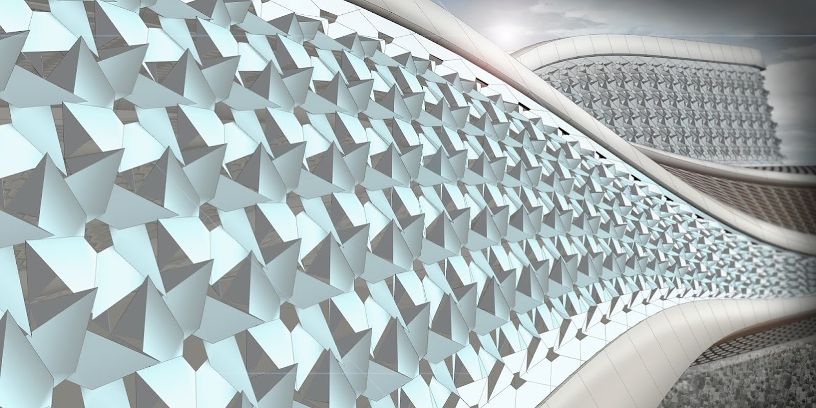
In this section, we will work through a simple exercise file that is meant as an introduction to working with Element tools. We will explore some patterning and facade treatments in the field of Architecture which will incorporate Half Edge data structures along with basic Element components without the use of per vertex features.
2.1.5.1 Example 1
Example files that accompany this section: Download
| 00. | Create a meshplane in Rhino with XFaces = 2 & YFaces = 2 and Start a new definition, type Ctrl-N (in Grasshopper) | |
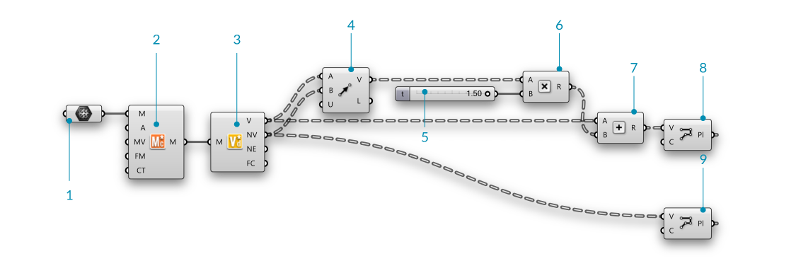
| 01. | Params/Geometry/Mesh - Drag and drop a Mesh container onto the canvas |  |
| 01b. | Reference a mesh in Rhino by right-clicking the Mesh component and selecting "Set one Mesh". We are going to use a simple mesh plane to walk through the definition, feel free to swap out the mesh with your own mesh |
|
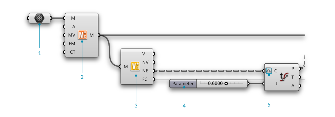
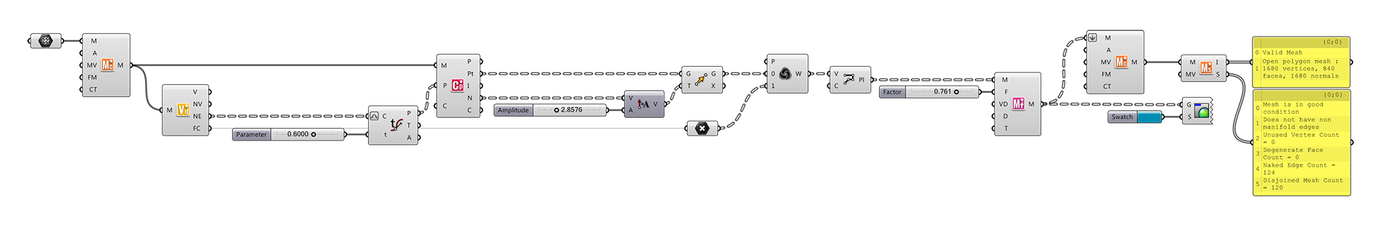
| 02. | Element*/Utility/Mesh Combine and Clean - Drag and drop a Element* Mesh Combine and Clean component on the canvas |  |
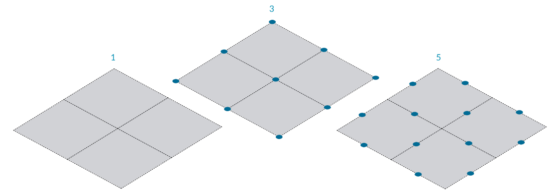
| 03. | Element*/Data/Vertex Neighbors - Drag and drop the Element* Vertex Neighbors component onto the canvas |  |
| 04. | Params/Input/Number Slider - Drag and drop a Number Slider component onto the canvas and set the following values:
Upper Limit: 1.0000 |
|
| 05. | Curve/Analysis/Evaluate Curve - Drag and drop a Evaluate Curve container onto the canvas |  |
| 05b. | Connect the Neighbouring Edges (NE) output of the Element* Vertex Neighbors component to the Curve (C) input of the Evaluate Curve component | |
| 05c. | Connect the Number Slider to the Float (t) input of the Evaluate Curve component and set the value to 0.5000 | |
| 05d. | Right click the Curve (C) input of the Evaluate Curve component and enable Reparameterize |
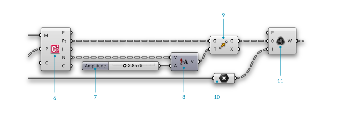
| 06. | Element*/Analyse/Mesh Closest Point - Drag and drop a Element* Mesh Closest Point container onto the canvas |  |
| 06a. | Connect the Mesh output (M) of the Element*/Utility/Mesh Combine and Clean component to the Mesh (M) input of the Element* Mesh Closest Point component | |
| 06b. | Connect the Points output (P) of the Curve/Analysis/Evaluate Curve component to the Point (P) input of the Element* Mesh Closest Point component | |
| 07. | Params/Input/Number Slider - Drag and drop a Number Slider component onto the canvas and set the following values:
Lower Limit:0 Upper Limit: 10.000 |
|
| 08. | Vector/Vector/Amplitude - Drag and drop a Amplitude component onto the canvas |  |
| 09. | Transform/Euclidean/Move - Drag and drop a Move component onto the canvas |  |
| 10. | Params/Geometry/Point - Drag and drop a Point container onto the canvas |  |
| 10b. | Connect the Face Centers output (FC) of the Element* Vertex Neighbors component to the Point component | |
| 11. | Sets/List/Weave - Drag and drop a Weave component onto the canvas |  |
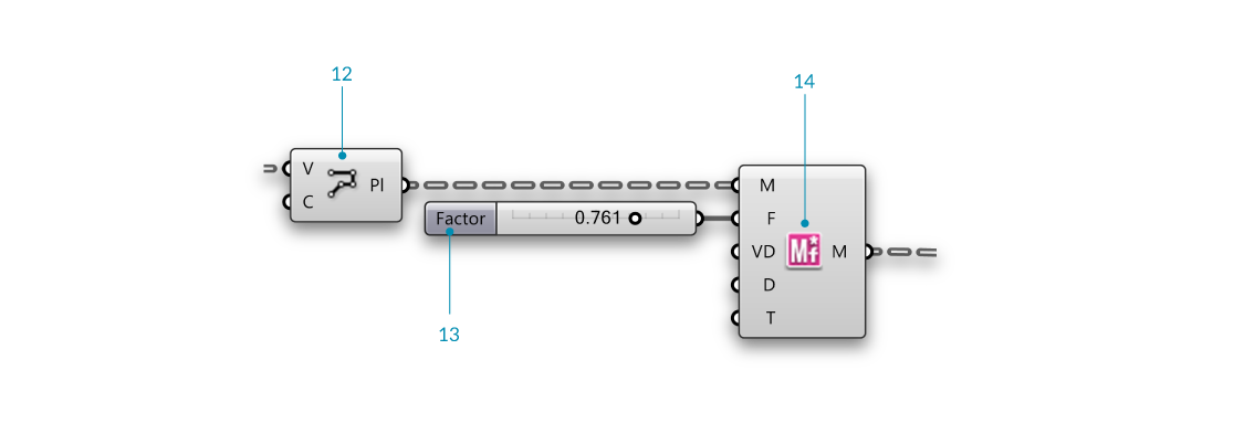
| 12. | Curve/Primitive/Polyline - Drag and drop a Polyline component onto the canvas |  |
| 12b. | Connect the Weave output (W) of the Weave component to the Vertices (V) input of the Polyline component | |
| 12c. | Right click the Closed (C) input of the Polyline component, click "Set Boolean" and set the value to True This has created a closed polyline. |
|
| 13. | Params/Input/Number Slider - Drage and drop a Number Silder component onto the canvas. We will keep the default range of 0 to 1 for this slider | |
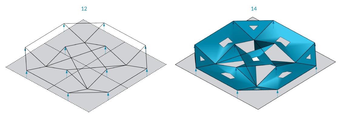
| 14. | Element*/Transform/Mesh Frame - Drag and drop a Element* Mesh Frame component onto the canvas. |  |
| 14b. | Connect the Polyline (Pl) output of the Polyline component to the Geometry (G) input of the Mesh Frame component Note that the **Mesh Frame** component can take either meshes or a list of closed polyline curves as input |
|
| 14c. | Connect the Number Slider to the Factor (F) input of the Mesh Frame component |
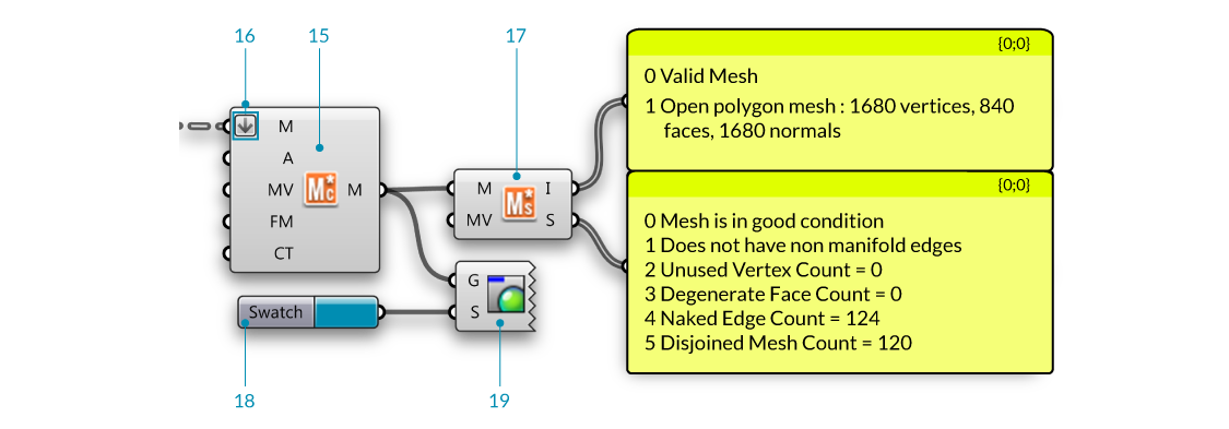
| 15. | Element*/Utility/Mesh Combine and Clean - Drag and drop a Element* Mesh Combine and Clean component on the canvas |  |
| 15b. | Right click the Combine Type (CT) input of the Element* Mesh Combine and Clean component, click "Set Integer" and set the value to 1. The Combine Type input has two options (0, which combines and cleans the meshes) and (1, which joins the meshes in the list without merging vertices). In this example we want to join the meshes |
|
| 16. | Right click the Mesh (M) input of the Element* Mesh Combine and Clean component, click "Flatten". This will flatten the list so we can join the mesh list together. |
|
| 17. | Element*/Utility/Mesh Status - Drag and drop a Element* Mesh Status component on the canvas |  |
| 17b | Connect the Info (I) and Status (S) outputs of Element* Mesh Status to a Params/Input/Panel component The mesh **Info** output contains mesh validity information, closed or open type and mesh component counts (vertices, faces, normals). The mesh **Status** informs the user if the mesh is in "Good" condition as well as data regarding non manifold edges, unused vertex count, degenerate face count, naked edge count and disjoined mesh count. |
|
| 18. | Params/Input/Colour Swatch - Drag and drop a Colour Swatch component on the canvas | |
| 19. | Display/Preview/Custom Preview - Drag and drop a Custom Preview component on the canvas |
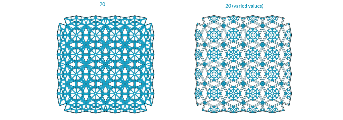
2.1.5.2 Example 2
Example files that accompany this section: Download
| 00. | Create a meshplane in Rhino with XFaces = 2 & YFaces = 2 and Start a new definition, type Ctrl-N (in Grasshopper) | |
| 01. | Params/Geometry/Mesh - Drag and drop a Mesh container onto the canvas |  |
| 01b. | Reference a mesh in Rhino by right-clicking the Mesh component and selecting "Set one Mesh". We are going to use a simple mesh plane to walk through the definition, feel free to swap out the mesh with your own mesh |
|
| 02. | Element*/Utility/Mesh Combine and Clean - Drag and drop a Element* Mesh Combine and Clean component on the canvas |  |
| 03. | Element*/Data/Vertex Neighbors - Drag and drop the Element* Vertex Neighbors component onto the canvas |  |
| 04. | Vector/Vector/Vector2Pt - Drag and drop a Vector2Pt component onto the canvas |  |
| 05. | Params/Input/Number Slider - Drag and drop a Number Slider component onto the canvas and set the following values:
Lower Limit:0 Upper Limit: 2.000 |
|
| 06. | Maths/Operator/Multiplication - Drag and drop a Multiplication component onto the canvas |  |
| 07. | Maths/Operators/Addition - Drag and drop two Addition components onto the canvas |  |
| 08. | Curve/Primitive/Polyline - Drag and drop a Polyline component onto the canvas |  |
| 09. | Curve/Primitive/Polyline - Drag and drop a Polyline component onto the canvas |  |
| 10. | Params/Input/Number Slider - Drag and drop a Number Slider component onto the canvas and set the following values:
Lower Limit:0 Upper Limit: 1.000 |
|
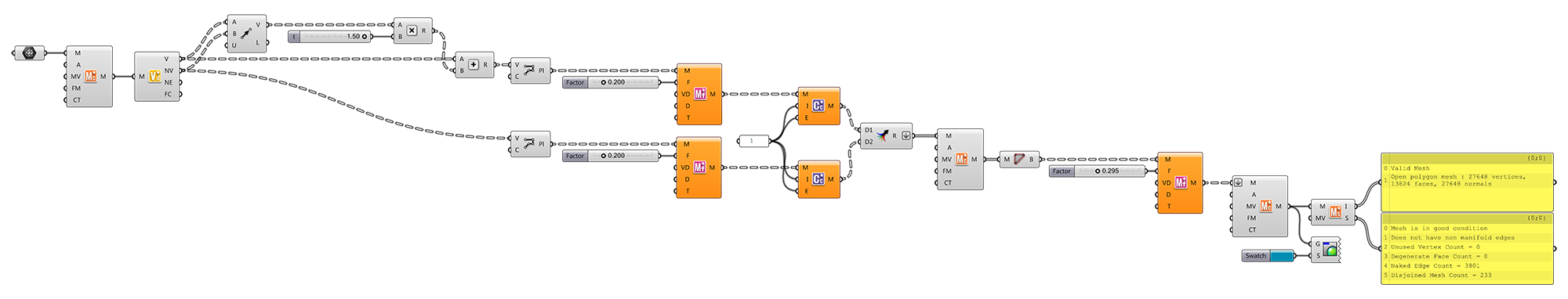
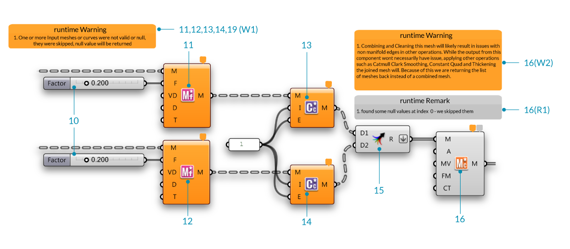
| 11,12. | Element*/Transform/Mesh Frame - Drag and drop a Element* Mesh Frame component onto the canvas. |  |
| 11b,12b. | Connect the Polyline (Pl) output of the Polyline component to the Geometry (G) input of the Mesh Frame component Note that the **Mesh Frame** component can take either meshes or a list of closed polyline curves as input |
|
| 11c,12c. | Connect the Number Slider (10) to the Factor (F) input of the Mesh Frame component | |
| 13,14. | Element*/Subdivide/Catmull Clark Subdivision - Drag and drop a Catmull Clark Subdivision component onto the canvas We will set the Iterations input (I) value to 1 as well as the **Edge Condition** input (E) to a value of 1. The edge condition input options are 0 = Fixed, 1 == Smooth, 2 == Corners Fixed. |
 |
| 15. | Sets/Tree/Merge - Drag and drop two Merge components onto the canvas |  |
| 15b. | Right click the Result (R) output of the Merge component and click "Flatten". | |
| 16. | Element*/Utility/Mesh Combine and Clean - Drag and drop a Element* Mesh Combine and Clean component on the canvas |  |
Components have detailed remarks and warnings to inform the user of the current or potential issues that might come about from interaction with other components. In some instances you might use the Element Combine and Clean component to join and combine identical vertices on a mesh which could lead to non manifold edges if that mesh is thickend later on. The Element Combine and Clean component will inform you of this issue that will return the list back to you. You have the option of setting the Combine Type to a value of 1 which will combine the meshes in the list but not combine identical vertices.
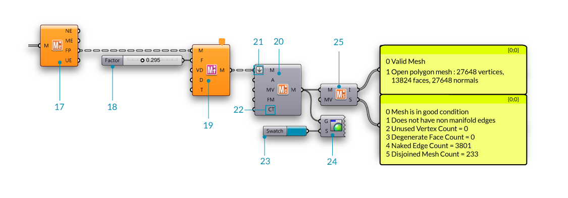
| 17. | Element*/Utility/Mesh Edges - Drag and drop a Element* Mesh Edges component on the canvas | 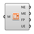 |
| 17b | Connect the Mesh (M) output of the Element* Mesh Combine and Clean component (16) to the Mesh input (M) of the Element* Mesh Edges component | |
| 18. | Params/Input/Number Slider - Drag and drop a Number Slider component onto the canvas and set the following values:
Lower Limit:0 Upper Limit: 1.000 |
|
| 19. | Element*/Transform/Mesh Frame - Drag and drop a Element* Mesh Frame component onto the canvas. |  |
| 19b | Connect the Face Polylines (FP) output of the Element* Mesh Edges component to the Mesh input (M) of the Element* Mesh Frame component | |
| 19c | Connect the Number Slider to the Float (f) input of the Element* Mesh Frame component | |
| 20. | Element*/Utility/Mesh Combine and Clean - Drag and drop a Element* Mesh Combine and Clean component on the canvas |  |
| 21. | Right click the Mesh (M) input of the Element* Mesh Combine and Clean component and click "Flatten". | |
| 22. | Right click the Combine Type (CT) input of the Element* Mesh Combine and Clean component, click "Set Integer" and set the value to 1. The Combine Type input has two options (0, which combines and cleans the meshes) and (1, which joins the meshes in the list without merging vertices). In this example we want to join the meshes |
|
| 23. | Params/Input/Colour Swatch - Drag and drop a Colour Swatch component on the canvas | |
| 24. | Display/Preview/Custom Preview - Drag and drop a Custom Preview component on the canvas | |
| 25. | Element*/Utility/Mesh Status - Drag and drop a Element* Mesh Status component on the canvas | 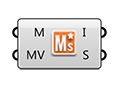 |
| 25b | Connect the Info (I) and Status (S) outputs of Element* Mesh Status to a Params/Input/Panel component The mesh **Info** output contains mesh validity information, closed or open type and mesh component counts (vertices, faces, normals). The mesh **Status** informs the user if the mesh is in "Good" condition as well as data regarding non manifold edges, unused vertex count, degenerate face count, naked edge count and disjoined mesh count. |